(EN) Análisis de vibraciones para principiantes 5
25.01.2024
1. ¿Qué es importante saber sobre el procesamiento de señales?
2. ¿Cuáles son las reglas básicas para evaluar la vibración de una máquina?
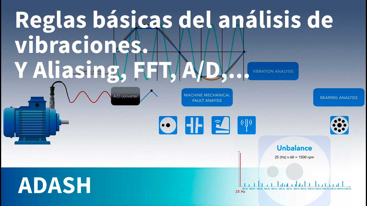
La señal de un sensor de vibración está en forma analógica. Para poder trabajar con ella en los analizadores, la señal debe convertirse a forma digital. Esta conversión se realiza mediante un conversor A/D.
Si la señal continua original contiene frecuencias superiores a la mitad de la frecuencia de muestreo, la señal se distorsionará por el fenómeno conocido como aliasing.
Ahora tenemos una señal digital en el analizador de vibraciones y podemos trabajar con ella. Por ejemplo, podemos mostrarla en su forma de dominio temporal: la forma de onda temporal. Sin embargo, una representación más informativa es el dominio de frecuencia. Como se muestra en el video anterior, el espectro revela las frecuencias que componen la señal de vibración. Para calcular el espectro, utilizamos la Transformada Rápida de Fourier (FFT).
La FFT tiene una limitación: todos los componentes de la señal deben ser periódicos.
Observamos que cuando la señal no es periódica, la energía "se escapa" o "se filtra" en varias líneas espectrales cercanas a la frecuencia real, lo que hace que el espectro se extienda en varias líneas; este fenómeno se denomina fuga. Para mitigarlo, se utiliza un truco: la señal se une artificialmente mediante ventanas, lo que la hace periódica.
El análisis de vibraciones se puede dividir en dos categorías: análisis de fallas mecánicas de la máquina y análisis de cojinetes. Las fallas mecánicas básicas de la máquina incluyen desequilibrio, desalineación y holgura mecánica. Podemos detectar estas fallas a frecuencias bajas (10 - 1000 Hz). Las mediciones de vibración se miden en velocidad (mm/s). Si los valores de velocidad son altos, el examen del espectro puede ser útil. Si el espectro muestra una sola línea alta en la frecuencia de velocidad, la falla es desequilibrio. Por ejemplo, si solo hay una línea alta a 25 Hz, calcular 25 x 60 da 1500 RPM. Si la velocidad es efectivamente de 1500 RPM, la falla es desequilibrio.
El desequilibrio puede ser mecánico, requiriendo balanceo, o eléctrico (en el caso de los motores). Para diferenciarlo, observe el valor de velocidad cuando el motor está apagado. Si el valor de velocidad disminuye a medida que disminuye la velocidad, la falla es desequilibrio mecánico. Una caída rápida a casi cero (corte de energía) indica una falla eléctrica. Si la línea de velocidad y sus múltiplos (armónicos) están presentes en el espectro, la falla es holgura o desalineación. Los valores de velocidad axial significativamente inferiores a los valores radiales (por ejemplo, menos del 30% del valor radial) sugieren holgura. En este caso, las lecturas deben tomarse en todos los pies de la máquina. Esto se puede hacer sin almohadillas porque las mediciones de velocidad a bajas frecuencias son menos sensibles que las mediciones de aceleración de alta frecuencia. Localice el pie con el valor más alto; probablemente indique la falla por holgura. Esto suele deberse a un perno de anclaje roto. Si el valor de la velocidad axial es similar o superior al valor radial, la falla es desalineación, que requiere alineación. Un tipo único de falla es la resonancia, que se imita como un desequilibrio con una sola línea de velocidad en el espectro. El equilibrio tendrá un efecto mínimo, ya que el problema real es la frecuencia natural de la base de la máquina cerca de la frecuencia de velocidad. Para identificar esto, mida la velocidad en la base. Si los valores son bajos en los extremos y altos en el medio, la resonancia es el problema. Por lo general, se requiere el fortalecimiento de la base; esto cambiará la frecuencia natural. El otro aspecto del análisis de vibración es el análisis de cojinetes. Las fallas de cojinetes ocurren en el rango de alta frecuencia (500 Hz a 16 kHz) y están representadas por las vibraciones del cojinete, un tono, causado por los impactos de bolas. La aceleración (g) se utiliza para medir la vibración. Un aumento en las vibraciones en el espectro de alta frecuencia indica un empeoramiento de la condición del cojinete. El análisis de cojinetes se centra en las frecuencias de falla que son específicas de los cojinetes. ¿Qué es una frecuencia de falla de cojinete? Imagine una picadura en la pista exterior. Cada bola que golpea la picadura provoca un choque de vibración (el tono). Si hay una grieta en la pista exterior, calculamos el intervalo de tiempo (T) entre los choques en función de la frecuencia de velocidad y el número de bolas. Este intervalo de tiempo define la frecuencia de repetición de los choques: la frecuencia de falla. En este ejemplo, es la frecuencia de falla de la pista exterior.
Pero las frecuencias de falla del rodamiento no aparecen en el espectro del rodamiento; solo es evidente la frecuencia de vibración del impacto de la bola (tono del rodamiento). Un impacto de bola de este tipo se puede ver en el dominio del tiempo:
Para identificar las frecuencias de falla, se utiliza la demodulación de la señal.


