Unlock the Power of Machine Labels in DDS
29.07.2025
The Machine Labels window indicates which frequencies are shown by labels.
These are speed frequencies, gear mesh frequencies, and bearing fault frequencies. We have machines that are running at a stable speed. In this case we just set one value of speed into DDS. On the other hand, there are also machines which change the speed. In this case it is important to use a tacho probe which we can define anywhere at the machine. All you need to do now is to learn how to create DSS tree structure correctly.
Machine Labels are available for spectrum and time signal measurements.
We created schema of the machine we use. It has a motor, gearbox, and fan. The gearbox has 13 teeth on the input shaft and 23 teeth on the output shaft.
We measure spectra and time signals at four points on this machine. These are P1 on the motor, P2_in and P2_out on the gearbox, and P3 on the fan.
We measure speed frequency of the motor with a tacho probe at its output shaft.
Speed frequencies at different parts of the machine To calculate speed at other measurement points, we must define gear ratios because our gearbox modifies the speed frequency.
There are two ways to do this. First way of doing it is at the points themselves in the Speed tab. Points P1 and P2_in measure speed at the same shaft as where the tacho probe is. It means that their gear ratios are 1.
We know the gearbox has 13 teeth on the input shaft and 23 on the output shaft, so the gear ratios at P2_out and P3 must be 13 divided by 23, or 0.565. We set the location of all measurement points to General.
The second way to define gear ratios is to keep it as 1 at every measurement point and define gear ratio at the gearbox item. This is where the speed change actually happens, so this approach is more straightforward.
However, it is important to define point locations for P2_in and P2_out. The gearbox has a different value of speed at its input and output shafts. We must consider this. The location for P2_in is Input. It is Output for P2_out.
Labels in spectrum These settings are sufficient to label speed frequencies, but not gear mesh or bearing fault frequencies. To see these as well, we must define gears and bearings at our machine.
Gear mesh and bearing fault frequencies For the gearbox of our machine, we go to the Gears tab, add a gear stage, and define the number of input shaft teeth and output shaft teeth there. This skips the need to define gear ratios manually and allows DDS to calculate gear mesh frequencies. Note that if we define gears like this, we must set correct Point Locations of the points P2_in and P2_out. This is because it is no longer possible to set them as Input or Output. There is now a stage on the Gearbox. We must set the point locations to Stage 1 input and Stage 1 Output. A gear mesh frequency can now be labelled in the spectrum.
User Bearing Database If we want to display bearing fault frequencies, we must define bearings in our machine. But we must create the User Bearing Database first. We may define our own bearings there. To do so, we must know a bearing’s dimensions. NB is the number of roller elements, BD is the roller element diameter, PD is the pitch diameter, and CA is the contact angle.
A new bearing may also be defined by coefficients for fault frequencies, where FTF is fundamental train frequency, BSF is ball spin frequency, BPFO is ball pass frequency outer, and BPFI is ball pass frequency inner. If these coefficients are multiplied by speed, we get the frequencies of bearing faults.
DDS has a large built-in database of bearings as well. We may import as many of these as we want into the User Bearing Database.
Defining bearings in the machine Now we need to define bearings at Tree Items or Points. There are two ways how to do that. The first way is to use the Bearings tab in Properties.
The second option is to define bearings at gear stages.
Let’s add a bearing to Fan. We access the User Bearing Database we have set up and add a bearing to the Fan.
We may redefine which ring of the bearing is fixed.
Spectrum with a gear and bearing Now we can see labels for the gear mesh frequency and bearing fault frequencies as well. We may also check in the window which specific bearing fault frequencies we want to display or not.
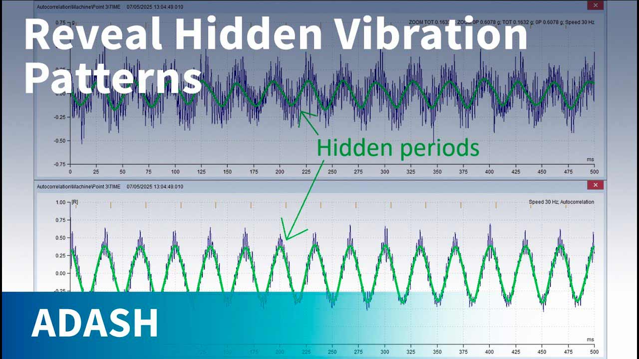
Time Signal of the same If a bearing in the machine is damaged, we may see shocks from bearing faults in the time signal. For example, we display the BPFI. In this case, the bearing’s inner race indeed has a fault or faults. This is obvious, because the shocks in the graph are perfectly aligned with the periodic cursor showing the BPFI.
But if we decide to display, other faults frequencies, they do not align with any shocks in the graph. This means the bearing does not have other kinds of faults.